Sabre Fonic Fence Perimeter Intrusion Detection
- Features & Benefits
- Specifications
- Documents
- FAQs
- Automatic environmental compensation minimises nuisance alarms
- Performance is unaffected by lightning or other electromagnetic interference
- Provides cost-effective linear protection for zones up to 1000 metres in length
- Easy to set-up and install without test equipment
- Operating parameters can be remotely adjusted using optional software
- Integral data collection when used with StarWatch in-built audio assessment capability
- Ease of installation
- Cost effective for small and large applications
- Simple and intuitive to use
- Suitable for high-security applications
- Field proven reliability even in difficult environments
- Low maintenance
- Low nuisance alarm rate
- Ideal for use with welded mesh or chain link fences
Power
- Power Requirement
- 11.0 – 14.0V DC @ 300mA
Processor
- High performance microcontroller with integral digital signal processor (DSP) and Analogue-to-digital (A to D) converter
Method of Detection
- Laser diode transmitter with speckle pattern detection using
photo diode receiver
Alarm Output Relay
- Up to 1A @ 12V DC
Ancillary Outputs (Open Collector)
- Two open collector outputs with a maximum rating of 100mA @ 24V DC.
Status / Digital Inputs
- 3 tamper protected status inputs are available which may be derived from switches or relay contacts, open collectors or CMOS / TTL level digital signals
- The digital signal inputs provide the means by which external equipment may control the unit’s auto-threshold values
Serial Communications Ports
- 1 isolated RS232 / RS485 serial port for alarm transmission, remote set-up or diagnostics
- 1 non-isolated RS232 serial port for local high level diagnostics
Installation, Test and Diagnostic Aids
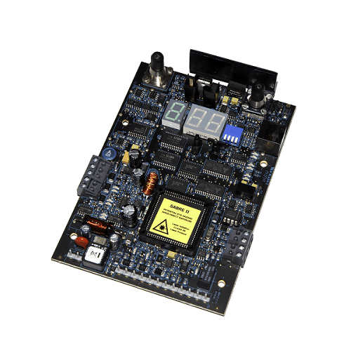
- The Sabre II PCB incorporates a simple user interface comprising toggle switch, push-button and 3 seven-segment displays and allows all necessary settings to be easily configured without the need for specialist test equipment. A number of operation and diagnostic LED indicators are also included to facilitate test and commissioning. An audio monitor output is also available which may be used as an additional commissioning aid. An optional PC based software package is available to enable local or remote, high level test, set-up and diagnostics.
Connections
- Electrical connections to the PCB are made via quick disconnect screw terminals. Serial communications cabling is via PCB mounted RJ 45 connectors
Environmental Specification
- Operating Temperature Range: -10°C to + 70°C
- Operating Humidity: up to 95% at +40°C non-condensing
- Storage Temperature Range: -40°C to +70°C
Electromagnetic Compatibility (EMC)
- Sabre II meets the requirements of EN55022: 1998, EN50082-1: 1998 and Low Voltage Directive 93/68/EEC.
Dimensions
- Printed Circuit Board: 158mm x 111mm
Listed below are some of the Frequently Asked Questions we receive for Sabre. Please contact us if you need more information.
Q: What is the maximum zone length of SabreFonic?
A: The maximum distance of fibre optic between the transmitter and receiver diodes is 1km. This means a maximum zone length of 500m in Cable / Fibre LOOP modes and 1000m in Box-Box mode.
Q: Do you have default parameter settings for Sabre II?
A: Yes, please contact us with your details and we will send you a guide.
Q: What size is the Sabre II Processor Unit?
A: IP 65 rated enclosure 400mm x 400mm x 200mm.
Q: What current does the Sabre II use?
A: 300mA @ 12vDC
Sabre II is a fibre-optic based Perimeter Intrusion Detection System (PIDS) and can protect many forms of physical barrier including fences, gates, walls, roofing and cover buried applications. Sabre II can sense and alarm for attempts to climb, crawl or sever the fencing. The technology uses a continuously monitored and intrinsically safe, fibre-optic sensor cable which is sensitive to vibration, flexing and compression.
Sabre II is designed for use with Remsdaq’s proprietary fence-mounted (SabreFonic) and buried (SabreLine) sensor cables. Disturbance of the fibre-optic sensor cable is detected in the Sabre II processor and analysed using a microcontroller with digital signal processor (DSP). When a disturbance exceeds pre-set conditions, an alarm will be generated. Automatic environmental compensation algorithms ensure the highest probability of detection whilst ensuring a minimum of nuisance alarms from natural causes.
Sabre II is factory set to enable rapid installation and commissioning.
Application specific set-up parameters can be adjusted in the field using built-in switches and an LED display. If required, Sabre II can also be configured and adjusted remotely using the integral serial communications ports and optional software tools.
Sabre II is especially useful for integration with third party data collection and alarm management systems. It provides facilities for external alarm threshold adjustment as well as additional input/output for connection of sensors or control devices.
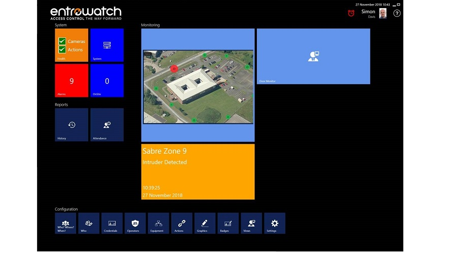
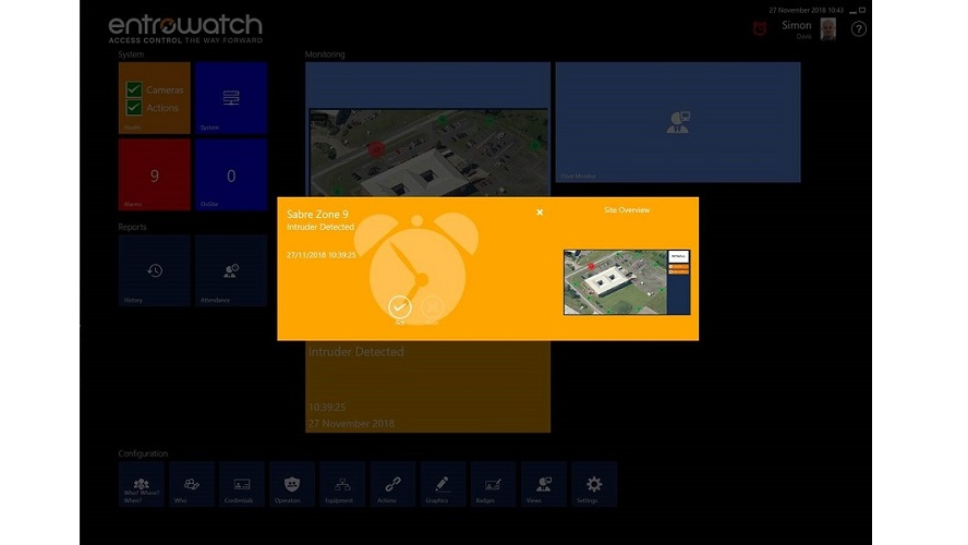
Sabre II with a BACNet/IP Gateway (see Documents tab for more information) can be monitored within EntroWatch access control software and other systems requiring IP connectivity.
Sabre II Technology
The Sabre II processor module combines digital signal processing and environmental compensation algorithms to provide the highest levels of detection and discrimination whilst ensuring a minimum of nuisance alarms due to natural causes. It also offers reliable classification of events including cut and climb. The Sabre II processor hardware is also used for SabreFonic (fence-mounted) and SabreLine (buried) sensor cables.
Sabre PIDS Configuration
This is a software configuration tool available for commissioning engineers to quickly and easily tune their SabreFonic or SabreLine installations locally from their PC.
- Simple and intuitive to use
- Choice of user languages
- Easy application of existing settings
- Integrated help with step by step channel commissioning guides
- Visual indications show when the peak signal exceeds configured thresholds
- Standalone application
Quick Enquiry Form
By continuing to use the site, you agree to the use of cookies. more information
The cookie settings on this website are set to "allow cookies" to give you the best browsing experience possible. If you continue to use this website without changing your cookie settings or you click "Accept" below then you are consenting to this.


