EntroPad Card Reader Connections
16 April 2020
This note outlines the technical aspects of the connections to EntroPad card readers. Further installation and configuration details are listed in the Related Documents section below.
The Remsdaq EntroPad series includes two RFID card reader models (card only or card plus keypad). The readers have industry standard Wiegand outputs and are designed for use with the Remsdaq EntroStar and EntroNet series of door controllers but can also be can be used as generic ID card readers with third party access control products. The EntroPad Management Kit allows the customisation of many of the EntroPad features including the following:
EntroPad Features
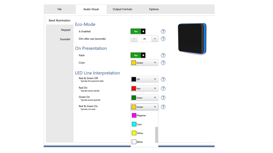
Lightband Colours
The colour of the EntroPad lightband can be configured to one of 8 available colours for each of the four possible combinations of the two LED control lines. When used with EntroStar or EntroNet controllers, its is also possible to control the colour and when the keypad digits are illuminated.
Keep Alive
For additional security, a binary code is sent on the Wiegand data connections every few seconds. In the event that the controller does not receive this code, it registers a tamper alarm to signal failure of the reader, loss of power or disconnection. A unique “tamper” code is also sent if the mechanical tamper is triggered.
Pin Descriptions
The reader connections are presented on an RJ-45, 8-pin socket. Pins are numbered from left to right when looking into the socket with the tab at the bottom.
| Pin Number | Designation |
|---|---|
| Pin 1 | +12VDC |
| Pin 2 | 0V / GND |
| Pin 3 | Wiegand D0 O/P |
| Pin 4 | Wiegand D1 O/P |
| Pin 5 | Reader LED 1 I/P (Green) |
| Pin 6 | Reader LED2 I/P (Red) |
| Pin 7 | Sounder I/P |
| Pin 8 | Reader Tamper Signal O/P |
Pins 1, 2 Power and Ground
EntroPad readers require a DC supply of 14V nominal (10-16V range) at approx. 125mA
Pins 3, 4 Wiegand Data Output
The Data One (D1) and Data Zero (D0) signals are normally held at a logic high level until the reader is ready to send a data stream. The reader places asynchronous low going pulses on the appropriate data line to transmit the data stream. Terminating resistors are not required.
Pins 5, 6 LED Control Input
The EntroPAD supports two reader LED inputs. The inputs to the EntroPAD are internally pulled up to Vcc (approx. +5V) via 10kOhm resistors. When pulled low (to 0V/GND) the LEDs are lit. In generic/defalut use the LEDs are Green (pin5) and Red (pin 6). If both inputs are activated the lightband will be Amber. The lightband colours can be customised using the EntroPad Management Kit.
Pin 7 Sounder Control Input
The sounder (buzzer) control input to the EntroPAD is internally pulled up to Vcc via a 10kOhm resistor. When pulled low (to 0V/GND) the sounder operates.
Pin 8 Tamper Detect
A micro-vibration sensor is used to provides a 3-axis mechanical movement/shock detection. When Tamper is enabled (default) the output goes high when movement is detected. To avoid multiple transitions on the line for a single event, the line is not retriggered for approx. 10 seconds. (Note: EntroNet controllers do not support this wired tamper, see Keep Alive). It is recommended to disable the mechanical Tamper (using the management kit) if the reader is mounted on a less than rigid structure (or in a moving application e.g. in an elevator car or onboard a ship).
Remsdaq Part Numbers
| Part Number | Description |
|---|---|
| EN-PX-R-W-R-X | EntroPad (no keypad) |
| EN-PX-KP-W-R-E | EntroPad with English Keypad |
| EN-PX-MT-K-RW-X | EntroPad Management Kit (software, 8 programming cards + EntroPad RW + USB cable) |
| EN-PX-MT-C-X-X | EntroPad Management Card Set (8 programming cards) |
Related Documents
| Number | Document Title |
|---|---|
| INS-15-001 | EntroPad Installation Guide |
| INS-18-001 | EntroPad Configuration Tool |
These documents are available upon request.
Here is a downloaded copy of this Remsdaq technical note.