11kV Network Automation With United Utilities
3 January 2017
United Utilities is a multi‐utility operator with extensive water, waste, telecommunications and electricity distribution operations based in the North West of England. United Utilities is also responsible for the delivery of electricity to more than 2 million customers. Their distribution network serves a number of urban conurbations, including Manchester. There is also an extensive overhead line network extending as far north as the Scottish border.
Automation of a Rural 11kV
This case study focuses on a largely rural area known as South East Macclesfield. This is an area characterised by an extensive 11kV overhead line network, comprising a number of long radials that serve small villages, farms and a number of industrial customers. Being located at the edge of The Peak District National Park, the network suffers some severe weather conditions and is therefore prone to permanent line faults. Heavy snowfall can make access difficult for restoration and repair teams.
United Utilities’ Requirement
The implementation of comprehensive network automation is seen as an integral part of United Utilities’ strategy to deliver improved service quality and reliability by reducing customer minutes lost and customer interruptions. The United Utilities requirement involved the supply, installation and integration of automation, control and communications equipment at a number of HV plant locations on the overhead network as well as ground mount equipment at supporting secondary substations. The project also called for the connection and integration of the automation scheme within the existing telecontrol infrastructure.
The Solution Remsdaq’s CallistoIES intelligent electronic system is the platform for this automation scheme and now provides monitoring, control and automation facilities at a number of automation and control points on the network. Overhead equipment consists mainly of Whipp and Bourne GVR Reclosers and Morris Line Air Break Switches (ABS). A variety of ground‐mounted plant, located at secondary substations, has also been automated within the scope of this project.
The Automation Project
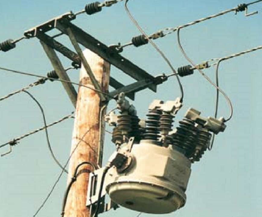
A Typical Overhead Circuit Although a variety of different line configurations exist in the network, for the purpose of this case study, a typical circuit consists of two, independently fed, radial circuits which form an ‘open ring’ via a normally open point (NOP), facilitated by an air break switch. At each in‐feed, a GVR recloser forms a source breaker. At quarter points (QP), a GVR recloser is installed. Additional recloser or ABS units have been installed in most circuits to provide additional localisation and isolation in the event of a fault.
HV Circuit Protection
Source breakers and other GVR reclosers in the circuit are configured to provide auto‐reclosing over‐current, earth fault and sensitive earth fault protection and sequencing. A Whipp & Bourne POLARR relay, installed in each GVR control cabinet, provides the protection functions.
Automation Installation
A suitably equipped CallistoIES unit, mounted on a custom plate and pre‐wired for rapid field‐based installation, was installed into each GVR cabinet and connected to the SCADA port of the POLARR relay. CallistoIES has an integral power supply and charger unit, which is fed by a 240V supply derived from a pole‐mounted voltage transformer. A sealed lead / acid standby battery was also installed in each cabinet to support CallistoIES in the event of a supply fault. A UHF digital radio transceiver and pole mounted antenna complete the installation.
At each ABS location, similar automation facilities have been installed, with the CallistoIES unit and transceiver being installed within the motor control cabinet.
An Automation Master Point Unit (AMPU) has been established in a nearby primary substation. This serves all circuits currently included in the scheme and provides for future expansion. The AMPU is a multi‐node CallistoIES system that serves as a data concentrator, automation controller and telecontrol interface. A GPS time‐code receiver and a UHF radio base station are also located here.
Communications System
The scheme utilises UHF radio (MPT 1411) for data communications between field units and the AMPU. The base station operates in a polling mode and where distance or terrain dictate, remote sites communicate via a repeater. The client’s chosen protocol, IEC 60870‐5‐101, is employed throughout the system.
Typical Automation Logic Operation
The GVR units located at source breaker points and recloser positions operate normally, according to individual configurations within each POLARR relay. Scheme logic is triggered only when a source or quarter point GVR lockout signal is detected. The logic then runs a pre‐defined switching sequence using the circuit breakers of source GVR, the quarter point GVR and the ABS at the NOP, in order to establish the location of a faulted line section.
Once the faulted section is located, the logic will complete the switching operation, restoring power to the healthy sections. The automation logic reconfigures a faulted circuit within the OFGEM restoration time criteria. All logic written for this scheme runs in the CallistoIES system at the AMPU, although the CallistoIES at each GVR or ABS location is also
capable of running its own automation logic, if required.