Urban Secondary Distribution Network Automation
9 March 2018
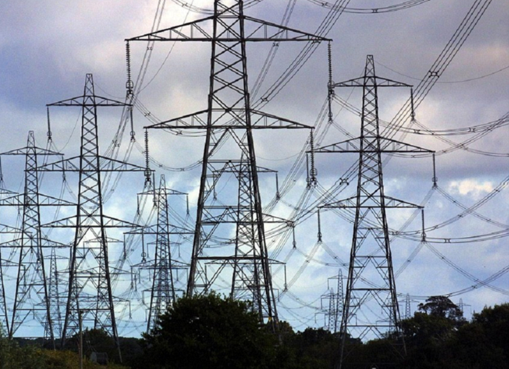
London Power Networks (LPN), part of The London Electricity Group, supplies electricity to more than 2 million customers in the London area and maintains a network comprising some 29,000 km of underground cable. This network has a high load and customer density and supports much of the infrastructure of the capital city. The loss of a single feeder could affect many thousands of customers, including central government, major corporations and The Stock Exchange.
The Problem
The most common faults in LPN’s network are invariably permanent and often attributed to accidental damage to underground cables, caused during construction work taking place in the city.
The network is designed such that each feeder can normally derive its supply from two separate sources. In most cases, restoration of customer supply simply involves local switching action using a Ring Main Unit (RMU), located at each secondary substation.
Due to the difficulties of traffic congestion, plant and personnel access, cable repair times are often very long. Even getting an engineer to a substation to throw the switch and restore supply could take two hours at peak times! In common with other UK utilities, LPN has to meet strict criteria for supply continuity, with strict penalties for supply interruptions and customer minutes lost.
LPN’s Requirement
The initial requirement was to provide remote control facilities for a number of RMU locations throughout the network. Switching could then be quickly undertaken by an operator in the network control centre. This has since been extended to include full network automation at selected locations, enabling immediate and automatic switching to take place following a feeder fault.
The Solution
LPN has now installed 5000 Callisto RTUs in its secondary network. The RTUs communicate with two control centres via trunked radio or, at locations where radio coverage is difficult, over PSTN telephone circuits. At the control centres, LPN use Remsdaq’s own Celeste HMI software for monitoring, control and configuration activities.
Key Benefits
The system has demonstrated that it can assist in delivering improvements in the quality of supply—as extracts from a recently published LPN paper highlight:
- “Customer satisfaction has improved considerably and complaints concerning MV faults have fallen to an all time low”.
- “very significant improvement in all of the standard rolling year reporting measures”.
The Project
Each Callisto RTU is supplied in a wall mount enclosure, installed in close proximity to the RMU and connected to it by means of a standardised umbilical cable. This cable has been designed effectively as ‘plug‐and‐play’, allowing the RTU to be rapidly connected to any one of several different RMU types in service on the network.
The RTU monitors plant using conventional digital inputs and a number of transducerless AC analogue inputs. The RTU receives status information from the RMU, local fault passage indicators and circuit breakers. Substation fire and security alarms are also monitored.
Individual feeder phase voltages and currents are measured on the LV side of the power transformer. Transformer oil and ambient air temperature are monitored using conventional analogue transducers. RMU controls are undertaken using highly secure command output relays within the RTU.
The RTU is mains powered and charges an integral heavy‐duty battery back‐up system. Battery condition is continuously monitored and automatic battery tests are undertaken periodically by the RTU. The RTU supplies power for the radio or PSTN modem. The RMU Actuator is powered directly from the RTU battery.
Communications
Most of the RTUs communicate via MPT 1327‐ based trunk radio transceivers, mounted within the RTU enclosure. Where radio coverage is unviable, a PSTN modem is fitted. Remsdaq’s own RPI protocol is employed; this is optimised for trunk radio operation.
The trunked radio system is structured around a network of six base stations, located at hill‐top sites and arranged to provide an overlapping coverage pattern. The base stations time‐share a number of radio channels for communication with RTUs. Each base station is individually connected to the control centre by a leased line.
SCADA System
At the two control centres, data is gathered from the RTU network using Remsdaq’s Celeste HMI, configured in a networked, client/server system of PCs operating under Windows NT. Celeste also includes a number of communications servers arranged in a fully redundant configuration. These interface directly to the PSTN and leased line modems.
Network Automation Functions
Although originally conceived as a remote control scheme, the system now incorporates extensive auto‐restoration functions. This automation has been implemented both at the local level using RTU logic, to make source switching an automatic process, and at the network level, where restoration and sectionalising logic routines, involving switching at multiple sites, reside in the Celeste Master. More than 1200 11kV circuits have now been automated in this manner.
Power System Measurements
The RTU delivers a significant amount of useful information including continuous provision of maximum 8‐day average values of load current and degree of balance in supply phases. LPN plan to extend the use of this information to incorporate condition monitoring of plant and cables.
A Callisto RTU as supplied to LPN showing a local control panel mounted on the cabinet door.
5,000 units have been supplied to‐date for this project
References:
1 & 2. Walton, C., “Remote Control of Urban 11kV Distribution Systems in London Electricity” ‐ a colloquium paper for “Remote control and Automation on 11kV Networks Beyond the Primary Substation”, 1999, The Institution of Electrical Engineers.